Careers   |   View Cart

Discuss your application 1.800.343.8008 | [email protected] | Follow on LinkedIn

Elmet Technologies

Request Quote
Menu
  • SHOP
    • Shop Molybdenum
      • Molybdenum Fasteners
      • Molybdenum Hex Nuts
      • Molybdenum Threaded Rod
      • Molybdenum Washers
      • Molybdenum Foil
      • Molybdenum Plate
      • Molybdenum Powder
      • Molybdenum Rod
      • Molybdenum Sheet
      • Molybdenum Wire
    • Shop Pure Tungsten
      • Tungsten Foil
      • Tungsten Plate
      • Tungsten Powder
      • Tungsten Rod
      • Tungsten Sheet
      • Tungsten Wire
      • Shop Tungsten Heavy Alloy
        • Class 1 Type 2 Tungsten (WHA) Bars
        • Class 1 Type 2 Tungsten (WHA) Blocks
        • Class 3 Type 2 Tungsten (WHA) Blocks
      • Shop TZM
        • TZM Plate
        • TZM Rod
        • TZM Sheet
    • Shop Lanthanated Moly
      • Lanthanated Molybdenum Sheet
    • Customer Resources and Data
      • Data Sheets and Material Data
      • Molybdenum Wire / Rod Calculations
      • Tungsten Wire / Rod Calculations
      • Weight Calculators
      • News
      • Shipping & Returns
  • Tungsten
    • Tungsten Foil
    • Tungsten Sheet
    • Tungsten Plate
    • Tungsten Rod
    • Tungsten Wire
    • Tungsten Cubes
    • Tungsten Spheres
    • Tungsten Powder
    • Tungsten Machining
    • Tungsten Heavy Alloy
    • Shop Tungsten
  • Tungsten Heavy Alloy
    • ASTM B777 – AMS 7725 Overview
      • ASTM B777 Class 1
      • ASTM B777 Class 2
      • ASTM B777 Class 3
      • ASTM B777 Class 4
      • Low Mag vs. Non Mag WHA Options
      • Where & Why Tungsten Heavy Alloy is Used
      • Is Your Tungsten DFARS Compliant?
    • 100% US Produced B777 WHA
      • WHA for Medical Shielding & X-Ray Imaging
      • WHA for Defense & Warhead Parts
      • WHA for Aerospace & Defense Applications
      • Tungsten Kinetic Energy Penetrators
      • Tungsten & Heavy Alloy Cubes
      • Tungsten & Heavy Alloy Spheres
      • Tungsten Heavy Alloy Product Data Sheet
    • Tungsten Heavy Alloy Form Factors
      • Tungsten Heavy Alloy As Sintered Blocks
      • Tungsten Heavy Alloy Plate
      • Tungsten Heavy Alloy Rod
      • Tungsten Heavy Alloy Sheet
      • Tungsten Fragmentation Parts
      • Machining and Fabrication
      • Weight Calculators
    • Shop Tungsten Heavy Alloy
      • Class 1 Type 2 Tungsten (WHA) Blocks
      • Class 1 Type 2 Tungsten (WHA) Bars
      • Class 3 Type 2 Tungsten (WHA) Blocks
  • Molybdenum
    • Molybdenum Foil
    • Molybdenum Sheet
    • Molybdenum Plate
    • Molybdenum Rod
    • Molybdenum Wire
    • Molybdenum Powder
    • Thermal Spray Powders
    • Molybdenum Machining
    • Glass Melting Electrodes
    • Molybdenum Threaded Rod
    • Shop Molybdenum
  • Materials & Alloys
    • The Elmet Advantage
      • Refractory Metals Overview
      • Data Sheets and Material Data
      • Weight Calculators
      • Molybdenum Wire / Rod Calculations
      • Tungsten Wire / Rod Calculations
      • About
    • Molybdenum
      • Molybdenum Foil
      • Molybdenum Sheet
      • Molybdenum Plate
      • Molybdenum Wire
      • Molybdenum Rod
      • Molybdenum Powder
      • Thermal Spray Powders
      • Molybdenum Machining
      • Glass Melting Electrodes
      • Shop Molybdenum
    • Tungsten
      • Tungsten Foil
      • Tungsten Sheet
      • Tungsten Rod
      • Tungsten Plate
      • Tungsten Wire
      • Tungsten Cubes
      • Tungsten Spheres
      • Tungsten Powder
      • Tungsten Machining
      • Shop Tungsten
      • TZM Alloy
        • TZM Sheet
        • TZM Plate
        • TZM Rod
        • TZM Machining
        • TZM Wire
        • Shop TZM
      • HCT Molybdenum
        • HCT Molybdenum Rod
        • HCT Molybdenum Wire
      • Lanthanated Molybdenum
        • Lanthanated Moly Sheet
        • Lanthanated Moly Plate
        • Lanthanated Moly Rod
        • Lanthanated Moly Wire
        • Lanthanated Moly Machining
        • Shop Lanthanated Molybdenum (MoLa)
      • Tungsten Heavy Alloy
        • Tungsten Heavy Alloy Sheet
        • Tungsten Heavy Alloy Plate
        • Tungsten Heavy Alloy Rod
        • Tungsten Heavy Alloy Machining
  • Key Segments
      • Molybdenum and Tungsten Fasteners
        • Molybdenum Threaded Rod
        • Molybdenum Hex Nuts
      • Defense and Warhead Parts
        • Tungsten Kinetic Energy Penetrators
        • Tungsten Heavy Alloy
        • TZM Forging Dies
        • Molybdenum Forging Billets
        • Blast Fragmentation Sleeves
        • Tungsten Fragmentation Parts
        • Elmet’s Expanding Cubes & Spheres Capabilities
      • Molybdenum Sputtering Targets
        • Molybdenum Sputtering Target Sizes
        • Sputtering Target Production
        • Sputtering Target Materials
        • Sputtering Target Bonding
      • Molybdenum Sintering Boats & Carriers
      • Studs and Heat Sinks
      • Tungsten & WHA Cubes
      • Tungsten & WHA Spheres
      • Refractory Metal Machining
        • Molybdenum Machining
        • Tungsten Machining
        • Tungsten Heavy Alloy Machining
        • Lanthanated Moly Machining
        • TZM Machining
      • Mo and W Crucibles
        • Tungsten Crucibles
        • Molybdenum Crucibles
      • Thermal Spray Powders
      • Tungsten and Molybdenum Hot Zones
        • Furnace Components
        • TZM Sheet
        • Molybdenum Sheet
        • Molybdenum Threaded Rod
        • Molybdenum Hex Nuts
        • Molybdenum and Tungsten Fasteners
      • Molybdenum & Tungsten Powder Products
      • Molybdenum Glass Melting Electrodes
      • Semiconductor Tooling Components
  • Mill Products
    • Rod Products
      • Molybdenum Rod
      • Tungsten Rod
      • TZM Rod
      • HCT Molybdenum Rod
      • Tungsten Heavy Alloy Rod
      • Lanthanated Molybdenum Rod
      • Molybdenum Threaded Rod
      • Molybdenum Gun Drilled Rod
    • Wire Products
      • Molybdenum Wire
      • Tungsten Wire
      • HCT Molybdenum Wire
      • Lanthanated Molybdenum Wire
      • TZM Wire
    • Foil Products
      • Molybdenum Foil
      • Tungsten Foil
    • Sheet Products
      • Molybdenum Sheet
      • Tungsten Sheet
      • Tungsten Heavy Alloy Sheet
      • Lanthanated Molybdenum Sheet
      • TZM Sheet
    • Plate Products
      • Molybdenum Plate
      • Tungsten Plate
      • Tungsten Heavy Alloy Plate
      • Lanthanated Molybdenum Plate
      • TZM Plate
    • Powder Products
      • Tungsten Powder
      • Molybdenum Powder
      • Thermal Spray Powders
  • About
    • News
    • Careers
    • History
    • Industries
    • Capabilities
    • Elmet Locations
    • Made in the USA
    • Working at Elmet
    • Supplier Resources
    • Customer Resources
    • Contact Us

Tensile properties of R512E coated Nb—C103 manufactured using laser powder bed fusion (L-PBF)

Tensile properties of R512E coated Nb—C103 manufactured using laser powder bed fusion (L-PBF)

December 17, 2024 by Elmet Technologies

Tensile properties of R512E coated Nb—C103 manufactured using laser powder bed fusion (L-PBF).

Tyler DuMez ᵃ, Michael T. Stawovy ᵇ, Scott Ohm ᵃ

ᵃ Elmet Technologies, Coldwater, MI 49036, USA

ᵇ Elmet Technologies, Euclid, OH 44117 , USA

Highlights:

  • Grain growth was observed after common post-processing techniques.
  • HIP and coated material failed to meet the ASTM F3635 specification for strength.
  • The effect of grain growth on strength decreases exponentially.

PDF 📄 Tensile properties of R512E coated Nb—C103 manufactured using laser powder bed fusion (L-PBF)


Abstract

C103 is a niobium based refractory alloy commonly used in the aerospace industry. To protect the metal from high-temperature oxidizing environments, C103 is often coated with an environmental barrier coating. A common coating for this material is known as R512E, a disilicide slurry applied and cured with heat. This paper aims to determine the effects on mechanical properties of common post processing techniques used on C103 produced via laser powder bed fusion. Tensile specimens were produced in both horizontal and vertical orientations, post processed via hot isostatic pressing, coated, and further heat treatment to simulate a typical operating environment for the coated material. Tensile tests were then conducted at room temperature and compared to ASTM B654 standards for wrought C103. Strength decreased after HIP and coating but remained unchanged after further heat treat. Grain growth was evident after HIP and coat applications which is in direct correlation with decreasing strength and increasing ductility.

Keywords:
Nb-C103; Additive manufacturing; Laser powder bed fusion (L-PBF); Mechanical properties; Environmental barrier coating (EBC)


1. Introduction

During the Cold War and Space Race of the 1960’s, a high temperature material was needed that could handle the operating temperatures of thruster nozzles. The material needed to be able to withstand the thermal shock from resting in the cryogenic atmosphere of space to an operating temperature of 1300 °C just seconds after ignition. Refractory metals have the highest melting points of all the metals but are notoriously heavy. An alloy with a high melting point and low mass was desired. Several companies including Boeing, DuPont, and GE were simultaneously developing alloys for this application using niobium as a base metal, the lightest of the refractory metals. As many as 256 alloys in the C-series (niobium was previously called columbium, Cb) [1] were tested but the alloy which yielded the best combination of formability and high temperature properties was C103, Nb-10Hf-1Ti. Other niobium alloys that emerged successful from that time include FS-85 (Nb-10 W-28Ta-1Zr) and Cb752 (Nb-10 W-2.5Zr).
 
C103 demonstrates high melting temperatures, good strength at elevated temperatures and low density, all suitable attributes for space propulsion materials [2]. Demonstrating good weldability, this material is suitable for additive manufacturing (AM), specifically, laser powder bed fusion (L-PBF). Thruster nozzles typically have large diameters with thin walls which generate significant waste if machined from wrought bar. These components can also benefit from internal cooling channels that are not feasible to produce using traditional manufacturing methods. Additively manufacturing thrusters to near net shape and machining to finish is a cost-effective way to manufacture these parts, especially with the volatility of hafnium’s price and availability. However, refractory metals are extremely susceptible to oxidation and C103 is no exception. Rocket propellants often contain oxidizers which, when combined with the high temperatures of combustion, attack the base-metal forming loose oxide scales and undergo severe dimensional degradation [3]. To protect the material from oxidation under high temperature environments a silicide coating may be considered. Environmental barrier coatings (EBC) are designed to prevent catastrophic degradation of the substrate material under high temperature in air oxidizing environments. A common coating for this application is R512E (Si-20Fe-20Cr) [4,5]. This coating, in slurry form, allows for easy application on large and complex parts [5]. Existing literature presents the effects of cyclic oxidation on annealed sheets of coated C103 on mechanical properties. This study aims to identify the effects of R512E and other common post processing techniques on the mechanical properties of AM C103.
 
The mechanical properties of AM C103 with R512E coating will be evaluated and compared against common post-processing techniques, including hot isostatic pressing (HIP) and two different heat treat procedures. The motivation for this investigation is to demonstrate the effects of heat treatment on coated C103 AM parts.
 

2. Experimental materials and methods

2.1. Powder characterization

Spherical C103 powder was provided by H.C. Starck Solutions (now Elmet Technologies) that was manufactured using an electrode induction gas atomization (EIGA) process. Powder size distribution (PSD) was analyzed using a Microtrac S3500, providing results for D10, D50 and D90 as 11, 28 and 47 μm, respectively. Elemental composition of the powder was analyzed using the inductively coupled plasma (ICP) technique and interstitial gas analysis (IGA) was performed to measure oxygen content. The composition of both the powder and AM C103 falls within range of the ASTM standard for B654/B654 M [6]. AM powders commonly have increased levels of oxygen because the powders are passivated for safety which forms oxide layers [6]. Bulk density and Hall flow were measured at 4.9 g/cc and 11 s/50 g, respectively. Theoretical density of C103 is 8.85 g/cc. Scanning electron microscopy (SEM) was performed on a Thermo Fisher Scientific Axia ChemiSEM. SEM images of the feedstock can be seen in Fig. 1.


Powder Characterization

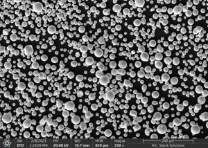
Fig. 1. SEM image of Elmet Technologies C103 powder for L-PBF.


2.2. Printing

Subscale tensile blanks were manufactured using a Renishaw AM400 in both horizontal and vertical print orientations on a pure titanium substrate. The oxygen setpoint of the machine was 100 ppm with argon as a shielding gas and without substrate heating. Layer height was 30 μm, energy density was 121 J/mm3 and the scan strategy was rotated 67° every layer. Horizontally printed blanks were removed from the plate with wire electrical discharge machining (EDM) and vertically oriented blanks were printed on supports and tapped off the build plate with a rubber mallet. Tensile blanks, as seen in Fig. 2, were then divided into five groups of three for further post processing. Density of parts were calculated using ASTM B962–17, Archimedes immersion density using 200 proof alcohol at 19°C. As-printed relative density was calculated to be greater than 99.5 %. Chemistry of the starting powder and printed material can be compared to ASTM B654 in Table 1.


Printing

Fig. 2. Vertical and horizontal tensile blanks.


Table 1. Element composition of ASTM sheet, starting powder and printed powder.

ElementASTM B654 (%wt)Starting Powder (%wt)As-printed (%wt)
NbBal.Bal.Bal.
Hf9–119.69.59
Ti0.7–1.31.00.89
Ta0.5 max0.20.28
W0.5 max0.20.27
Zr0.5 max<0.10.07
O0.035 max0.0270.029

2.3. Post processing
All of the tensile blanks were machined to ASTM E8 subscale specifications. Group one serves as an as-printed control with no post processing besides machining. Group two demonstrates the effects of only HIP and was performed on the blanks before machining to eliminate the risk of sagging during HIP. Parameters for HIP were 1593 °C at 103 MPa for 2 h per ASTM F3635–23.
 
Group three took specimens that were HIP’d and had the EBC applied. The vendor of the coating does not disclose the temperature used to apply the coating, but a study by Glass from 1997 suggests that the slurry coating is applied at 1426 °C for 1 h and is assumed for this experiment [7].
 
Further post processing included vacuum heat treating of group four and five at 1093 °C and 1426 °C for 3.33 h. Heat treat cycles for group four and five will be referred to as HT1 and HT2, respectively, in following figures. Fig. 3 outlines the post processing step for each group. The selected temperatures and pressures replicate the typical operating environment experienced by this material if used for spaceflight applications and 3.33 h is the demonstrated steady state firing duration of a production rocket engine with C103 components, specifically, the Aerojet Rocketdyne R-4D-11. Following heat treatment, all tensile bars were tensile tested at room temperature following ASTM E8 standards.
 
Post-processing

Fig. 3. Post Processing for Each Group of Printed Tensile Blanks.


3. Results and discussion

In this study, the tensile properties of AM C103 that was post processed using common techniques was compared to wrought C103.
 
The results in Fig. 4, Fig. 5 represent the average of three tensile specimens printed in each orientation compared to the ASTM B654 standard for wrought C103. As-printed C103 met or exceeded the specifications for ultimate tensile strength (UTS), yield strength (YS) and elongation (ε) for both vertical and horizontal print orientations. Specimens that were HIP’d resulted in lower tensile properties and the application of the coating further lowered the strength of the material while raising the ductility. Further heat treatment of the HIP + Coated specimens appeared to have little effect on the mechanical properties of the material.

 
Results discussion

Fig. 4. Tensile properties of horizontally printed tensile bars.


Results-discussion-2

Fig. 5. Tensile properties of vertically printed tensile bars.


3.1. Microstructure
A cross-section of a sacrificial sample from the same build plate was analyzed. EBC thickness measured 125 μm where half of the coating thickness is fused to the new material and the other half is added to the surface, as indicated by the porous material in Figs. 6. Through-thickness cracking is apparent in the coating caused by differing coefficient of thermal expansion (CTE) between the base metal and coating. This is typical of silicide coatings applied to Nb, Mo and W alloys [3]. The CTE of NbSi2 is higher than that of the base metal niobium, 7.3–11.7 μm°C-1 and 7–8 μm°C-1, respectively [3].
 
Microstructure

Fig. 6. Machined tensile bars. Middle: Machined and coated tensile bars. Right: SEM cross section of coated AM sample.


Assuming an application temperature of 1200-1400 °C, the coating experiences tensile stresses during the cooling process from application heat treat to room temperature. NbSi2 is inherently brittle and caused these through-thickness cracks [3]. Kumawat et al. conducted energy-dispersive X-ray spectroscopy (EDS) analysis near the cracks to determine if oxygen was able to penetrate the base material after vacuum heat treatment. The presence of oxygen was not detected suggesting that the interaction of oxygen and niobium did not occur during the coating formation heat treatment. This was assumed to be true for the current study.
 
Tensile bar grip ends that had been HIP and coated were analyzed using electron backscatter diffraction (EBSD) to analyze the crystallographic texture and grain structure as shown in Figs. 7. Although only the gauge length of the tensile bars had coating applied, the entire tensile bar was subject to the temperatures required to cure the slurry. Planes normal to build direction (BD) and perpendicular to BD were observed. EBSD inverse pole figure (IPF) taken normal to BD reveals random yet equiaxed grains. Perpendicular to BD reveals columnar grains favoring 〈112〉 crystal orientation. The average grain size normal to and perpendicular to BD was 159 μm and 164 μm, respectively. High temperatures from HIP and coating processes have been shown to cause grain grown in L-PBF AM parts and were evidenced in this experiment [8].
 
Microstructure-2

Fig. 7. Inverse pole figures taken normal to build direction (left) and perpendicular to build direction (right).


3.2. Grain Growth

Grain size is a key factor that determines the properties of metal alloys and can affect tensile strength, ductility, fatigue, hardness, thermal conductivity, etc. [9]. To determine if grain size was a cause for the change in tensile properties, grip ends from each of the tensile bars were etched and polished to measure grain size across the five groups. Table 2 shows the average grain diameters of each post processing step. C103 in the as-printed condition had the finest grain structure. Grain size grew roughly 250 % after hot isostatic pressing while yield strength decreased by 31 %. Grains grew another 15 % after the application of the coating and again the yield strength decreased, by 12 %. Grain size was not severely affected by HT1, although HT2 increased the grain size a further 15 % but had insignificant effect on tensile properties. The Hall-Petch relationship can be used to describe the relationship between yield strength and grain diameter using eq. 1, where d is the average grain diameter, k is a material dependent constant and σo is the friction stress.

Grain growth


Table 2. Grain size of vertically printed specimens after post processing steps.

Empty CellAs-printedHIPHIP + CoatHT1HT2
Normal to BD (μm)58142159158184
Perpendicular to BD (μm)63173164169199

Raw tensile test data was plotted on a true stress vs true strain curve to calculate σo and k. These values were then used to plot the Hall-Petch curve fit of the measured yield strength from each of the five groups against expected yield strength across various grain sizes as seen in Fig. 8. This curve fit suggests that as grain size gets larger its effect on yield strength is reduced. As-printed tensile bars from group one had the smallest grain size and the highest strength. Grain size grew with post processing treatments, however, the effect of grain size on strength is less pronounced as grain size increased.

Hall-Petch Curve

Fig. 8. Hall-Petch curve fit of yield strength vs grain size.


4. Conclusion

The tensile properties of C103 produced via L-PBF were successfully analyzed. If C103 is to be used in spaceflight applications, specifically in an oxidizing environment, the part is likely to be HIP’d and an environmental barrier coating is likely to be applied by the end user. The effects of these treatments have detrimental effects on the strength of this material. This research highlighted the effects of HIP, HIP + Coat, and HIP + Coat + vacuum heat treat and is highlighted below:
  1. As printed C103 is capable of meeting ASTM standards of wrought material for strength and elongation.
  2. HIP’d material showed significant grain growth and a decrease in strength yet continued to exhibit strength higher than the minimum requirement wrought material.
  3. The application of R512E again caused grain growth and lower strength, almost equal to wrought C103. EBC vendors should publish the application temperature and duration as it has a direct effect on the mechanical properties that the part designer may not be aware of.
4.1. Comparing to F3635-23 Standards

Per ASTM F3635–23, Class A parts in this method destined for spaceflight applications shall be processed by HIP and require a grain size of 3 to 5 or finer with UTS of 497 MPa, YS at 0.2 % offset of 347 MPa and elongation of 32 %. In the current study, the HIP procedure caused grain growth that exceeded the 3 to 5 (0.065–0.130 mm) requirement. This grain growth resulted in a decrease of strength that caused the material to fail the published standards for UTS and YS.


Credit Authorship Contribution Statement

Tyler DuMez: Writing – original draft. Michael T. Stawovy: Supervision, Writing – review & editing. Scott Ohm: Supervision, Writing – review & editing.

Declaration of competing interest

The authors declare that they have no known competing financial interests or personal relationships that could have appeared to influence the work reported in this paper.

Data availability

Data will be made available on request.
 
References
 
View references.

Filed Under: Manufacturing

Request a Quote

  • Max. file size: 50 MB.
  • This field is for validation purposes and should be left unchanged.

Quick Links

  • About
  • Refractory Metals Overview
  • Molybdenum
  • Tungsten
  • Defense and Warhead Parts
  • Refractory Metal Machining

Brochures

American Flag

Made in USA

News

ITAR

Certifications

Apply at Elmet

Contact Elmet

Request a call from our sales team.

  • Max. file size: 50 MB.
  • This field is for validation purposes and should be left unchanged.

Metals

  • Molybdenum
  • Tungsten
  • Lanthanated Moly Alloy
  • TZM Molybdenum Alloy

Mill Products

  • Rod Products
  • Sheet Products
  • Plate Products
  • Wire Products

Key Segments

  • Molybdenum Sputtering Targets
  • Defense and Warhead Parts
  • Refractory Metal Machining
  • Hot Zone Parts

About Elmet

  • Home
  • About
  • Industries
  • Made in the USA

1560 Lisbon St, Lewiston, ME 04240 | Connect on LinkedIn | Come Join Our Team!

FULLY INTEGRATED MANUFACTURER OF HIGH PURITY MOLYBDENUM, TUNGSTEN, TZM, MOLA AND WHA METALS

© 2025 Elmet Technologies | Terms of Service